Home-build lanterns

following a Belgian example

This was published in Modelspoormagazine 69 - more pictures and text can be found there...

Lanterns are sold in many forms. The better ones have a connector system, in order to remove these fragile parts from the layout if nescessary. But, what if you you'd like a particular lantern model manufacturers don't produce? A home-built lantern, including a connecting system, is the only answer...

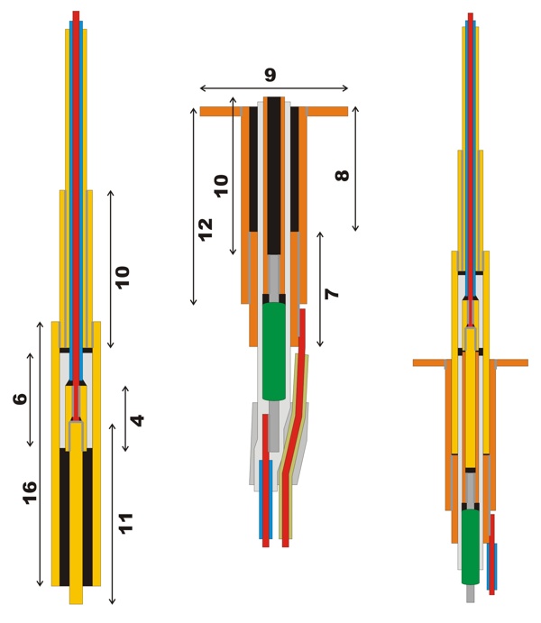
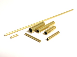
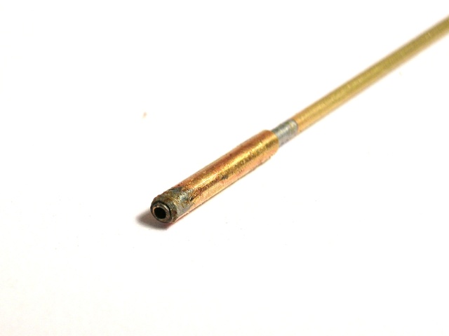
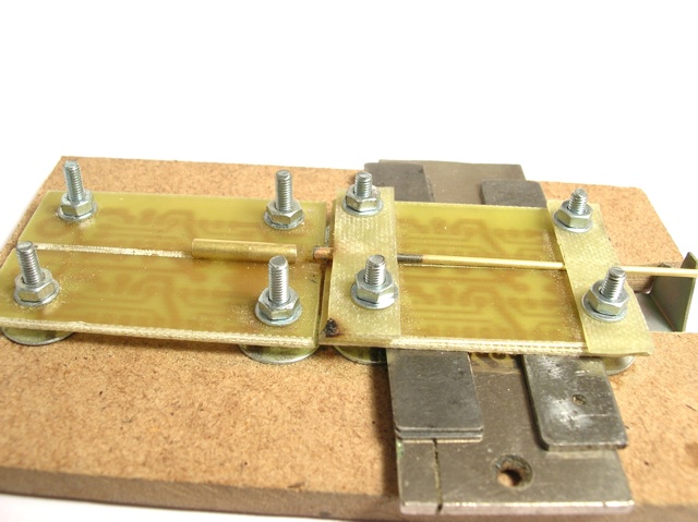
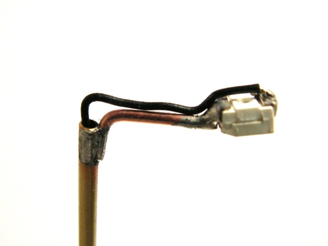
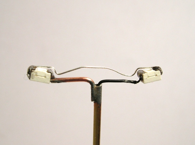
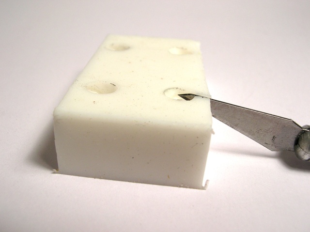
Electronics manufacturers have a huge number of connector types, but none of them seem to agree with the size or construction method of model lanterns. We don't need a complex connector, though. Two insulated poles, where one of them can be the conducting mantle of the lantern, is sufficient. After some experimentingwith various brass tubes and wires, I came to the following design:


The drawing shows the two connector halves and how they fit. The colors used have the following meaning:

  • Yellow: brass parts of the male connector
  • Orange: brass parts of the female connector
  • Red: copper wire (wire core)
  • Grey: soldered joints
  • White: insulations, made from shrinking tube
  • Black: hollow space within the connection
  • Blue and yellow: wire mantle (insulation)
  • Green: serial resistor, needed when using Leds

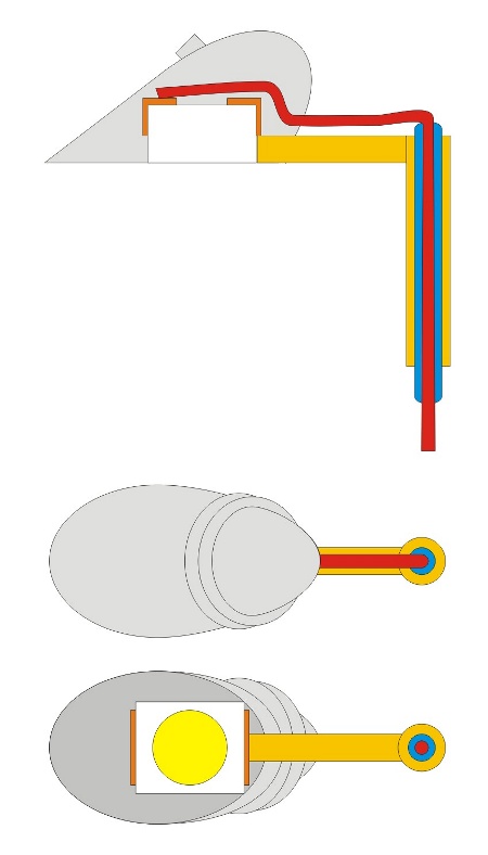
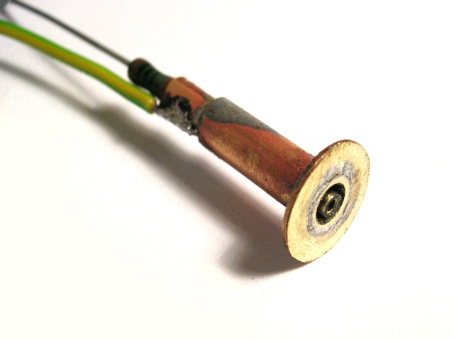
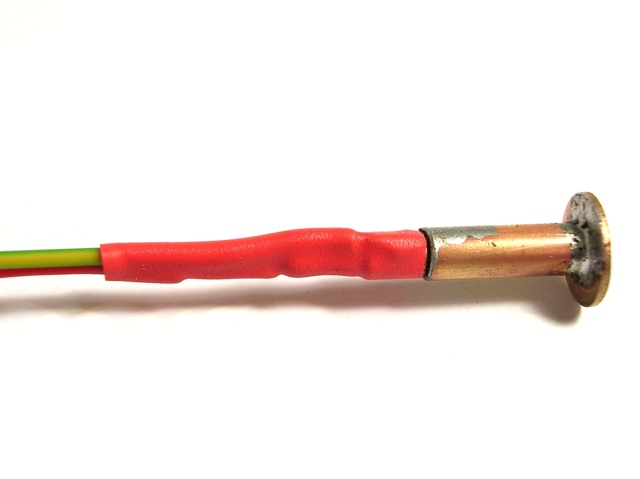
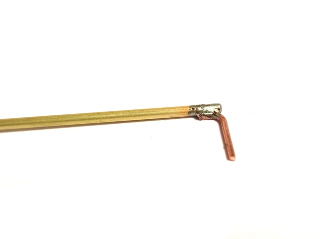
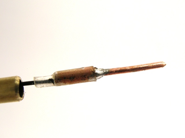
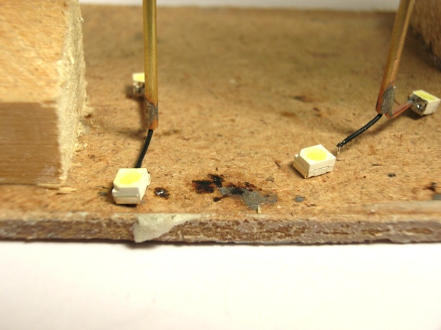
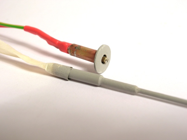
The male connector consists of a metal mantle and an isolated conducting core, fitting in a female part. This is made with two insulated tubes. The female connector, the lantern foot part, holds a serial resistor and has a brass ring, leveling it with the layout "ground".


The reason why I needed my own lantern type - and therefor my own connecting system - is the lantern model, frequently used on Belgian station platforms and even on city streets. As far as I could search, I didn't find these in H0 scale size.
The drawing shows the lamps' shape and how a very small SMD-type Led could be hidden and connected inside. To get the lamp hood "around" the light, I decided to resin-cast this using a silicon mould.
The construction desrciption is intended for small-series production. Along the way, I made some simple construction tools.


A first tool helps to cut and solder brass tubes and wires. It is made from a wooden board, an L-shaped metal plate, pertinax and some M3 nuts, washers and bolts. If you don't have any pertinax, get hold of some thermal resistant, non-conducting and solid sheet material. On this sheet, I first filed a 1mm deep gap lengthwise, and drilled 8 holes, corresponding to holes in the wood bottom board.
At one side of the bootom, a gap is cut to allow space for an L-shaped adjustable gauge. Some small pieces of pertinax are used as clamps and finish the tool.


A first usage of this tool is cutting pieces of tubing to length. For eachlantern post this means: three 1,3 mm thick tubes with a length of 4, 12 and 70 mm, one 2 mm tube thick and 10 mm long, two 3 mm thick lenghts of 7 and 12 mm, one 4 mm thick, 12 mm long.


Lets star soldering with the foot part. We take the thickest tube and the 7mm long, 3 wide tube. The last mentioned is clamped, the tool's height adjusted so the parts can slide easily. Using a quite hot soldering iron, they are connected.
The foot's brass ring is connected now, too .


A powermass-connection is soldered to this composition, taking care the wire is streamlined with the foot's body part.


The positive connection in our foot part is assembled using a 2mm thick,12mm long tube and a resistor, preferably a 1/8W type. These parts are alligned in our tool.
When using a thicker 1/4W type resistor, you should leave a 6mm long connection free, a smaller resistor canbe soldered close to to tube.


In our example, there's a gap between the tube and resistor, which should be shielded with using shrinking tube. A (possibly second) shrinking tube is placed over the whole length of the brass tube, to get an electrical insulation between the foot's core and its outer mantle.


The core part can now be assembled inside the mantle piece using instant glue. The core should be visible on the top side of the lantern foot to allow easy assembly of the top part of the lantern.


The lower resistor connecting wire gets a connecting wire, too. The whole foot part is now streamlined and secured using a wider piece of shrinking tube, insulating the foot's bottom part and all soldered connections.


We start the top part of the lantern by mounting the 2mm wide tube part over one side of the longest thin tube. The heated solder will flow easily to get a solid construction. File the end smooth and clean the inner part if needed, so the future wire can easily slide through the tube.


A 3mm wide, 12mm long broadening is fit at the end to get a good fitting connection with the foot part we made earlier. We definitely need our fitting tool to line them up, as the overlapping connection should be only 2mm long.


For our special light model, we need a short horizontal hanger, which is made from a piece of 0,8mm copper wire, bent to an L-shape. This is soldered with its short end at the top end of the lantern. Use lots of flux and only a bit of solder to get a smooth connection.


We need a second tool, made from scrap wood en some wash drying clamps. These clmaps are diassembled and mounted the other way, to form a sort of self-holding tweezers. One SMD can now be soldered at the lantern's hanger. Use the negative end of the SMD.


De lantern post's core is assembled from very thin mounting wire, a short thin brass tube and a piece of copper wire. The tube connects and alligns both wires. This connection should be insulated from the lantern's mantle using a piece of shrinking tube.
This core part will be shoved inside the foot's core, so sharpening the wire end is a good idea. After assembly with instant glue, the pointed end should stick out of the lantern's mantle by one mm.


Next big step: the light hoods. They will be cast in resin, so we need a master model to cast a silicon mould. Four master models are milled from a brass rod. The picture shows its forms.


The four master models are glued in a styrene-made box. Their location in this box should fit our "hanging-helper" we made earlier. The box is filled with silicon rubber to get a mould.


While the silicon sets, we can build the lamps further. A one-light lantern is easy: the central wire is bent in shape and soldered to the SMD-LED's other end.


A double-lamp lantern post is a bit more difficult: we need to solder a second SMD-LED to the central wire.


Connect the ends of both SMD's with a piece of wire to achieve a serial link. Using a thick black paint, the wires are insulated and the top side of the leds won't spread any light.


After a week, the silicon mould is hardened enough. We make some cuts in the mould to fit the connecting wires.


Four lanterns can "hang in there" at the same time. "There" is our previously resin-filled mould. The SMD's are fit in, their hanging height adjusted to "just-not" reach the resin surface.


When the resin has set, the cast forms can carefuly be pulled out of the mould. When connecting the lantern, light will emerge from the hood's top. We don't want this, and have to use some black paint to shield of the light.


The real paint job is best done with an airbrush. Be careful not to paint (block) the electric connection system or obstruct the SMD's light emision.


Placing the lanterns on the layout is quite simple: drill a 4mm hole and put the foot part in it. Connect it to a suitable power source.


When everything we have done is done fine, we now have easily removable lantern posts. Their light intensity should be regulated at will.

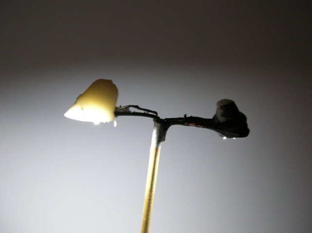
In this contrubution, I mostly wanted to tell about my home-made lantern post socket system.The specific lamp hoods are an extra item, and that's why this page is a bit longer than I intended. Nevertheless: have fun trying it out for yourself!

©2008 Gerolf Peeters - updated 01.10.2008 See: wall-lights - tubelights - semaphores